Technology Construction Gas Springs
How do gas springs work
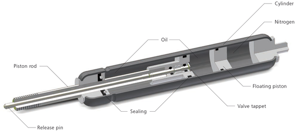
The internal pressure “P” of the nitrogen gas within the gas spring applies pressure against the cross sectional area “D” of the piston rod and gives the theoretical resultant force “F”
If fitted to a flap [hood, tailgate, etc.] which is already mounted, and the weight is not known, place a stick or pole under the far end of this flap [hood, tailgate, etc] with a set of bathroom scales underneath the pole.
If the flap [hood, tailgate, etc.] is of single piece construction, the distance (A) in the horizontal position is comparable with half the height of the flap [hood, tailgate, etc.]. If rafters or advertising boards hang on the far end, the distance (A) must be calculated, considering this. If you find difficulty in finding exactly the right gas springs, we will be happy to advise you.
In a cylinder housing a piston rod with a cross sectional area, “D” operates with a telescopic action.
The seal between piston rod and cylinder housing seals the inside of the gas spring against the atmosphere.
The internal pressure “P” of the nitrogen gas within the gas spring applies pressure against the cross sectional area “D” of the piston rod and gives the theoretical resultant farce “F”
Use conditions
Can be used from -30 to +80 degrees C (nominally 20 degrees C). The internal gas pressure rise/falls by 3.4% per 10 degrees
 Force Gas Spring
The force of a gas spring is given in N (Newton) (1 kg = 9,81 N).
Force tolerance
From 200 to 600 N ± 7%, thereafter ± 5%.
Margins of pressure
Due to the force tolerance and necessary reserve against extra external pressure on the gas spring caused by snowfall and/or wind squalls, a reserve pressure margin of + 10% should be taken into account when calculating the required force of the gas spring.
Impulse force (F4)
Push in the piston rod at a rate of max. 0.025 m/s, to 5 mm before full compression and held firmly. Read off the impulsion force.
Impulse force (F1)
1) Push in the piston rod once completely and allow it to extend, unhindered.
2) Push in the piston rod 10 mm at a maximum rate of 0.025 m/s, and held firmly
Read off the expulsion force.
Friction (Fw)
Push in the piston rod 5 mm at a maximum rates of 0.025 m/s and held firmly. Read off the force and from this deduct the force of expulsion. The difference is twice the friction.
Linearly force
The ‘progressive’ values at the gas spring are dependent on the ratio at the volume at the piston rod and the volume at nitrogen.
Towards the end at the stroke on standard springs, there is a rise in the expulsion force in the following percentages (isotherm).
Half Stroke Full Stroke
6/15 12% 27 %
8/18 14% 33 0/0
10/22 14% 33 %
14/28 20 % 50 %
20/40 14% 33 %
By various combinations of extension length, piston rod diameter and/or cylinder en unrestricted variation in progression is possible.
The raising of the internal pressure of the gas spring on very fast compression is, due to the related rise in temperature of the gas, at half stroke about 5 % higher than the values given in the table, and en full stroke about 12 %.
Installation
Due to the oil cushion present in standard gas springs, it is advisable to fit the piston rod facing the base. The oil cushion has three functions:
(1) Grease of the piston
(2) Grease of the sealing
(3) Serves as a soft end stop
Durability
The gas spring has an extensive life period if the gas spring is fitted in the correct (axial) way and the piston rod is kept free from dirt and damage.
 Attention
Gas springs contain high-pressure nitrogen, DO NOT OPEN.
The nitrogen is uninflammable so there is no danger for explosion.
Temperature
Standard gas springs are useable from -30°C until +80°C (normal 20°C)
The force chance with 3,4% at 10°C
Speed
The extention speed of a normal gas spring is approximate 500 mm / second.
Point A on the graph shows the gas spring extension characteristic and point B the compression
The damping happens both on extension and compression of the gas spring.